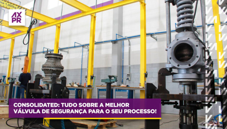
Continuing with the special series of articles on safety and relief valves, authored by Artur Cardozo Mathias, an expert in the field, we delve into details and characteristics of these valves and their applications.
In today's article, we will discuss the inlet piping of safety and relief valves, covering details of the design for valves protecting boilers and those safeguarding pressure vessels and pipelines.
-
Approximately 75% of all operational issues related to safety and relief valves are directly associated with incorrect installation.
Therefore, there are certain details that must be respected for the design of the inlet piping for these valves, such as:
- Internal diameter equal to or greater than the valve's inlet connection;
- Length of this piping equal to 5 times its nominal diameter or 200 mm, whichever is smaller;
- Pressure drop limited to 3% of the set pressure for valves protecting pressure vessels;
- 2% of the set pressure or 2 psi, whichever is greater (for valves protecting boilers);
- Installation always in the vertical position (up to 1° off vertical is acceptable);
- Where allowed, use only full-port block valves, gate valves, or ball valves, for example. However, in boilers, the use of block valves or any accessory between the boiler and the valve is expressly prohibited.
The pressure drop that occurs at the inlet connection of these valves reduces their nominal flow capacity to a value lower than that originally stamped on their nameplate, thereby increasing the pressure inside the vessel.
This pressure drop is the differential pressure between the outlet of the protected equipment and the inlet of the valve when it is fully open and relieving.
It is produced by the fluid's friction in flow against the pipe wall.
The larger its value, the higher the pressure inside the vessel (and the lower the value of the pressure at the valve outlet). While it is closed, the pressure inside the vessel and at the valve inlet will be the same.
The pressure drop in a pipeline is directly proportional to the peak flow velocity of the fluid and the length of the pipeline, and inversely proportional to the diameter of the pipeline.
A pressure drop greater than 3% in this pipeline can cause an operational phenomenon called "chattering" of the disk against the nozzle, potentially damaging these components due to physical contact, damaging guide components, causing spring fatigue, and even preventing the valve from relieving excess pressure.
During the occurrence of this phenomenon, the disk does not reach the full stroke because there is only sufficient pressure to open the valve, but there is no pressure (and force) under the disk support sufficient to keep the valve fully open and relieving.
Chattering is a very rapid cycling (approximately 20 cycles per second!) of the moving components of the valve and occurs (mainly when the fluid is compressible), always at the same set pressure value.
Another common cause of chattering occurs when the flow rate released by the process is less than 30% of the maximum flow capacity through the valve (or less than 10% if the fluid is liquid). However, there are other causes for this phenomenon.
The flow rate used in the pressure drop calculation should be the nominal flow capacity stamped on the valve nameplate.
An excessive pressure drop in the inlet pipe can be even more harmful to a bellows-balanced valve or a valve with resilient seating, the latter regardless of whether it is conventional or balanced.
The 3% pressure drop limit is a recommended value in both the ASME Section VIII code (Appendix M6 (a)) and API Std. 520 Part II.
And beware, when installing safety and relief valves, also avoid:
- Entry of foreign materials into the outlet piping of the vessel or boiler. This is an area where there is normally no flow until the valve opens.
- If this care is not taken during the valve installation, it will be damaged the first time it operates.
- Therefore, in applications where solid particulates can accumulate in this area, it is recommended to reduce the inspection intervals.
- Installing these valves in long horizontal sections of piping where there is normally no flow.
- This lack of fluid flow in this region can cause the accumulation of residues or even condensate that tends to increase its opening pressure value, as well as limit or restrict the effective flow capacity of the valves, making them undersized or even inoperative!
- When it is not possible to follow this recommendation, a greater number of interventions should be planned for valve inspection and maintenance.
- Installing a safety and relief valve in the liquid space of a vessel containing vapor and liquid.
- If it is sized for vapor and is installed in the liquid space, it will be oversized undersized for this position.
- On the other hand, if it is sized for liquid and is installed in the vapor space, it will now be subdimensionada undersized for this position.
- If it is sized and specified for liquid, then install it in the liquid space.


